Raytracing!
This post has erratum.
Since I started programming I’ve had a dream in the back of my mind: raytracers are super cool, and I’d like to build one myself. But with that dream accompanied another thought: raytracers are nearly a pure expression of math, a discipline I am poorly qualified for.
However this winter I discovered a new programming community, OneLoneCoder, and its leader, javidx9. Watching the videos produced by javidx9 inspired me to take a leap of faith in myself and start this raytracing project. The result has been amazing to see unfold as I developed first a working prototype in C#, then in C++, and finally as I produced what hopefully is an easy to follow “tutorial” style Git repository. So, lets dive in!
What is Raytracing?
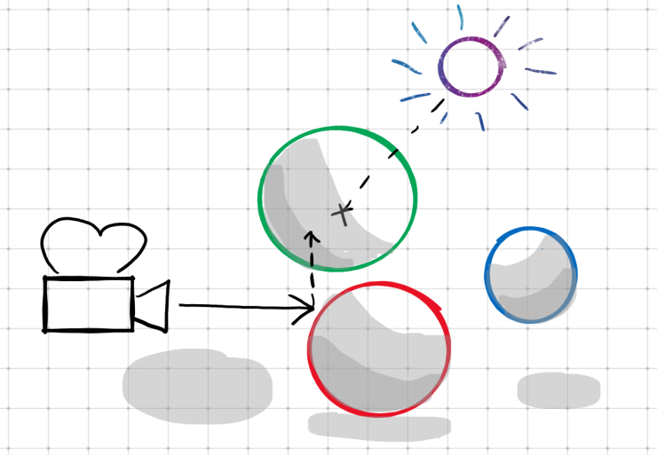
Raytracing is a method of rendering three dimensional scenes that is inspired by the physics behind light and vision. In the real world, light emanates from some source and bounces off of objects before entering our eye and being processed by the brain. In raytracing, however, this process is reversed, and a “ray” is sent out from the virtual camera into a scene, collecting information about the objects it encounters, eventually returning a resolved color for that pixel of the canvas.
How Do We Begin?
Creating a new olc::PixelGameEngine Project
We’re going to start with in Visual Studio (I’m using 2022). Select the (C++/Windows/Console) template. I also opted for the flat directory structure option: .

We copy in the olcPixelGameEngine.h file and add it to our solution. We also add a blank main.cpp
and populate it with the contents of the template available in the olcPixelGameEngine.h header, taking care to rename
our game class to match our needs.
Running our project will render a default PixelGameEngine scene: a 256x240 canvas of random pixels, magnified 4x:
 Click to zoom.
Setting the Scene
Add basic Shapes and a vector of shapes to render
We create a base class Shape and derived class Sphere (blank for now) that we will use to define our renderable
objects in the future.
We also add a std::vector of std::unique_ptr<Shape> to our game class. This will allow us to add new Shape-derived
objects to our scene:
shapes.emplace_back(std::make_unique<Sphere>());
When the game exits, the memory we allocated will be freed (thanks, smart pointers).
Add constants and a way to “Sample” single pixels
We define a few constants for window geometry and begin implementing our rendering process by looping over the rows and
columns of the scene and calling a Sample function that takes a floating-point x,y position on the viewport and
returns a olc::Pixel for that location.
// Game width and height (in pixels).
constexpr int WIDTH = 250;
constexpr int HEIGHT = 250;

// Half the game width and height (to identify the center of the screen).
constexpr float HALF_WIDTH = WIDTH / 2.0f;
constexpr float HALF_HEIGHT = HEIGHT / 2.0f;
bool OnUserUpdate(float fElapsedTime) override {
    // Called once per frame

    // Iterate over the rows and columns of the scene
    for (int y = 0; y < HEIGHT; y++) {
        for (int x = 0; x < WIDTH; x++) {
            // Sample this specific pixel (converting screen coordinates to scene coordinates).
            auto color = Sample(x - HALF_WIDTH, y - HALF_HEIGHT);
            Draw(x, y, color);
        }
    }

    return true;
}

olc::Pixel Sample(float x, float y) const {
    // Called to get the color of a specific point on the screen.
    // For now we're returning a color based on the screen coordinates.
    return olc::Pixel(std::abs(x * 255), std::abs(y * 255), 0);
}
Running our project will now render a 250x250 canvas at 2x magnification. Our magenta fill has been replaced with a color pattern converging in the center of the canvas:
Add some geometry types, enhance Shape and Sphere
We add structs for vectors (vf3d) and rays (ray). A vector represents a 3-dimensional point in space or a
3-dimensional magnitude, while a ray uses two vectors, one to represent an origin point, and one to represent a
directional magnitude out from that point.
// Struct to describe a 3D floating point vector.
struct vf3d {
    float x, y, z;
    // Default constructor.
    vf3d() = default;
    // Explicit constructor that initializes x, y, and z.
    constexpr vf3d(float x, float y, float z) : x(x), y(y), z(z) {}
    // Explicit constructor that initializes x, y, and z to the same value.
    constexpr vf3d(float f) : x(f), y(f), z(f) {}
};

// Struct to describe a 3D floating point ray (vector with origin point).
struct ray {
    vf3d origin, direction;
    // Default constructor.
    ray() = default;
    // Add explicit constructor that initializes origin and direction.
    constexpr ray(const vf3d origin, const vf3d direction) : origin(origin), direction(direction) {}
};
We’ll also enhance our Shape class with properties that will allow us to describe the size, position, and color of
shapes in our scene:
// Class to describe any kind of object we want to add to our scene.
class Shape {
public:
    vf3d origin;
    olc::Pixel fill;
    // Delete the default constructor (we'll never have a Shape with a default origin and fill).
    Shape() = delete;
    // Add explicit constructor that initializes origin and fill.
    Shape(vf3d origin, olc::Pixel fill) : origin(origin), fill(fill) {}
};
We’ll also give the Sphere class a notion of a radius, which is not shared by all Shape-derived classes:
class Sphere : public Shape {
public:
    float radius;
    // Delete the default constructor (see "Shape() = delete;").
    Sphere() = delete;
    // Add explicit constructor that initializes Shape::origin, Shape::fill, and Sphere::radius.
    Sphere(vf3d origin, olc::Pixel fill, float radius) : Shape(origin, fill), radius(radius) {}
};
Next, we’ll want to update our OnUserCreate function to pass in the newly required properties of a Sphere. Let’s
create our initial Sphere at the position x=0, y=0, z=200, where \(x\) is lateral position, \(y\) is vertical
position, and \(z\) is depth (or distance from the camera). Since our camera will be at x=0, y=0, z=0 this will
align our Sphere in the center of the canvas, 200 units away. We’ll also give our Sphere a solid olc::GREY color,
and set the radius to 100.
- shapes.emplace_back(std::make_unique<Sphere>());
+ shapes.emplace_back(std::make_unique<Sphere>(vf3d(0, 0, 200), olc::GREY, 100));
Finally, using our newly created ray type, let’s construct a ray in Sample for a given pixel that will point into
the scene:
// Create a ray casting into the scene from this "pixel".
ray sample_ray({ x, y, 0 }, { 0, 0, 1 });
// TODO: We now need to test if this ray hits any Shapes and produces
//       a color.
We create the ray at origin x=x, y=y, z=0, and set the direction to x=0, y=0, z=1. The direction is what we call a
unit vector, which means that the overall magnitude to the vector is 1 (\(\sqrt{x^2+y^2+z^2}=1\)). Using a unit vector
will simplify some math for us later.
Add fog color and a way to sample rays
To prevent our scene from extending into infinity, and to have something to show when a ray doesn’t hit anything, we add a new constant: a “fog” color.
// A color representing scene fog.
olc::Pixel FOG(128, 128, 128);
Additionally, we add a more specific function, SampleRay, that is called by Sample to return the color (or absence
thereof) of a ray as it extends into our scene. For now, still, this returns a color relative to the \(x\) and \(y\)
coordinate in our scene:
// Add a new include at the top of our file:
#include <optional>

// ---✂---

std::optional<olc::Pixel> SampleRay(const ray r) const {
    // Called to get the color produced by a specific ray.
    // This will be the color we (eventually) return.
    olc::Pixel final_color;
    // For now we're returning a color based on the screen coordinates.
    return olc::Pixel(std::abs(x * 255), std::abs(y * 255), 0);
    final_color = olc::Pixel(std::abs(r.origin.x * 255), std::abs(r.origin.y * 255), 0);
    return final_color;
}
Don’t forget to update Sample accordingly:
  // Create a ray casting into the scene from this "pixel".
  ray sample_ray({ x, y, 0 }, { 0, 0, 1 });
- // TODO: We now need to test if this ray hits any Shapes and produces
- //       a color.
+ // Sample this ray - if the ray doesn't hit anything, use the color of
+ // the surrounding fog.
+ return SampleRay(sample_ray).value_or(FOG);
Add intersection and sample methods to Shapes
Our SampleRay function has been upgraded to search for a Shape that it intersects with. To do this, Shape has been
upgraded with two new virtual methods:
// Get the color of this Shape (when intersecting with a given ray).
virtual olc::Pixel sample(ray sample_ray) const { return fill; }

// Determine how far along a given ray this Shape intersects (if at all).
virtual std::optional<float> intersection(ray r) const = 0;
These methods provide the ability to determine where along a ray a Shape intersects, and to provide the color of the
Shape at a given ray intersection. Our Sphere class overrides the intersection method, though for now
the implementation only returns an empty optional.
// Determine how far along a given ray this Circle intersects (if at all).
std::optional<float> intersection(ray r) const override {
    // TODO: Implement ray-sphere intersection.
    return {};
}
Finally, let’s update our Sample function, replacing the final_color value we compute based on screen coordinates
with an algorithm that searches a Shape that intersects with our given ray:
// Store a pointer to the Shape this ray intersects with.
auto intersected_shape_iterator = shapes.end();
// Also store the distance along the ray that the intersection occurs.
float intersection_distance = INFINITY;

/* Determine the Shape this ray intersects with(if any). */ {
    // Iterate over all of the Shapes in our scene.
    for (auto it = shapes.begin(); it != shapes.end(); it++) {
        // If the distance is not undefined (meaning no intersection)...
        if (std::optional<float> distance = (*it)->intersection(r)) {
            // Save the current Shape as the intersected Shape!
            intersected_shape_iterator = it;
            // Also save the distance along the ray that this intersection occurred.
            intersection_distance = distance.value();
        }
    }
    // If we didn't intersect with any Shapes, return an empty optional.
    if (intersected_shape_iterator == shapes.end())
        return {};
}
// Get the shape we discovered
const Shape &intersected_shape = **intersected_shape_iterator;
// Set our color to the sampled color of the Shape this ray with.
final_color = intersected_shape.sample(r);
Rendering Shapes
Implement ray-Sphere intersection
We’ll need to overload some operators for a vf3d: subtraction, and dot-product. A dot-product is a useful way of
comparing two vectors to determine if they are similar. Consider two vectors, \(a\) and \(b\). The dot-product is a
scalar value determined like so:
So, for example:
\[\begin{bmatrix} 1 & 2 & 3\end{bmatrix}\cdot\begin{bmatrix} 4 & 5 & 6\end{bmatrix}\newline=\newline(1\cdot4)+(2\cdot5)+(3\cdot6)\newline=\newline4+10+18\newline=\newline32\]Translating this to C++ gives us our dot product function:
// Dot product (multiplication): vf3d * vf3d = float
const float operator* (const vf3d right) const {
    return (x * right.x) + (y * right.y) + (z * right.z);
}

// Subtraction: vf3d - vf3d = vf3d
const vf3d operator-(const vf3d right) const {
    return { x - right.x, y - right.y, z - right.z };
}
We’ll also implement the equation for an intersection between a ray and a Sphere. I’m not going to go into depth
explaining the geometry here: this is a well-documented process and can be researched separately.
std::optional<float> intersection(ray r) const override {
    return {};
    vf3d oc = r.origin - origin;
    float a = r.direction * r.direction;
    float b = 2.0f * (oc * r.direction);
    float c = (oc * oc) - (radius * radius);
    float discriminant = powf(b, 2) - 4 * a * c;
    if (discriminant < 0)
        return {};
    auto ret = (-b - sqrtf(discriminant)) / (2.0f * a);
    if (ret < 0)
        return {};
    return ret;
}
Running our project will now render a (highly aliased and flatly-colored) Sphere!
 Click to zoom.
Add perspective rendering and depth sorting
First we’ll add some additional Spheres to our scene at different Z-depths. If we run our project now, you’ll see that the Spheres added to our scene last are drawn in front of the earlier ones, even if they are further away.
// Add some additional Spheres at different positions.
shapes.emplace_back(std::make_unique<Sphere>(vf3d(-150, +75, +300), olc::RED, 100));
shapes.emplace_back(std::make_unique<Sphere>(vf3d(+150, -75, +100), olc::GREEN, 100));
To remedy that, we up date our hit check in SampleRay to select the object whose intersection is nearest to the ray
origin. Now if we run our project, the Spheres are properly sorted.
- if (std::optional<float> distance = (*it)->intersection(r)) {
+ if (std::optional<float> distance = (*it)->intersection(r).value_or(INFINITY);
+                 distance < intersection_distance) {
However, you’ll notice that all three Spheres are the same size, despite being different distances from the camera. To
fix this, we’ll need to add perspective to our camera. We’ll do this in a very simplistic manner, by having all of the
rays originate from some point, and pointing towards what you can think of as a “virtual canvas” some distance in front
of that origin point. Update Sample like so:
- ray sample_ray({ x, y, 0 }, { 0, 0, 1 });
+ ray sample_ray({ 0, 0, -800 }, { (x / (float)WIDTH) * 100, (y / (float)HEIGHT) * 100, 200});

  // Sample this ray - if the ray doesn't hit anything, use the color of
  // the surrounding fog.
- return SampleRay(sample_ray).value_or(FOG);
+ return SampleRay(sample_ray.normalize()).value_or(FOG);
Notice we call method of ray that we haven’t defined yet: normalize(). Normalization produces a normalized vector
(discussed before) from a non-normalized vector by resizing the vector components in proportion to their length such
that the overall length is still 1. Normalization is defined as (with \(v\cdot{}v\) of course being the dot product of
itself):
Let’s add normalize() to both ray and vf3d:
// ---✂--- In ray:

// Return a normalized version of this ray (magnitude == 1).
const ray normalize() const {
    return { origin, direction.normalize() };
}

// ---✂--- In vf3d:

// Division: vf3d / float = vf3d
const vf3d operator/(float divisor) const {
    return { x / divisor, y / divisor, z / divisor };
}

// Return a normalized version of this vf3d (magnitude == 1).
const vf3d normalize() const {
    return (*this) / sqrtf((*this) * (*this));
}
By normalizing this ray we get rays properly fanning out in a perspective.
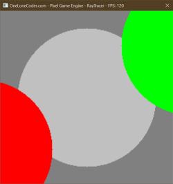
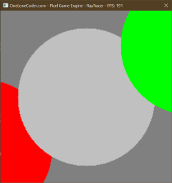
Running our project will now produce a proper perspective rendering of our three flat-shaded Spheres, at the correct depths.
 Click to zoom.
Open Image Comparison
Add a Plane Shape, and apply fog
First we’ll add a new type of Shape: a Plane. This is a flat surface extending infinitely in all directions. I’m not
going to go into depth about the intersection algorithm, as that’s basic geometry and is better explained elsewhere.
Unlike a Sphere, orientation matters to a Plane, so we’ll also add a “direction” vf3d that will indicate the
normal pointing away from the surface.
// Subclass of Shape that represents a flat Plane.
class Plane : public Shape {
public:
	vf3d direction;

	// Add explicit constructor that initializes
	Plane(vf3d origin, vf3d direction, olc::Pixel fill) : Shape(origin, fill), direction(direction) {}

	// Determine how far along a given ray this Plane intersects (if at all).
	std::optional<float> intersection(ray sample_ray) const override {
		auto denom = direction * sample_ray.direction;
		if (fabs(denom) > 0.001f) {
			auto ret = (origin - sample_ray.origin) * direction / denom;
			if (ret > 0) return ret;
		}
		return {};
	}
};
We will also override the sample virtual method for the first time to provide a checkerboard pattern that will make
the perspective rendering we added last time really pop.
// Get the color of this Plane (when intersecting with a given ray).
// We're overriding this to provide a checkerboard pattern.
olc::Pixel sample(ray sample_ray) const override {
	// Get the point of intersection.
	auto intersect = (sample_ray * intersection(sample_ray).value_or(0.0f)).end();

	// Get the distances along the X and Z axis from the origin to the intersection.
	float diffX = origin.x - intersect.x;
	float diffZ = origin.z - intersect.z;

	// Get the XOR the signedness of the differences along X and Z.
	// This allows us to "invert" the +X,-Z and -X,+Z quadrants.
	bool color = (diffX < 0) ^ (diffZ < 0);

	// Flip the "color" boolean if diff % 100 < 50 (e.g., flip one half of each 100-unit span.
	if (fmod(fabs(diffZ), 100) < 50) color = !color;
	if (fmod(fabs(diffX), 100) < 50) color = !color;

	// If we're coloring this pixel, return the fill - otherwise return DARK_GREY.
	if (color)
		return fill;
	return olc::DARK_GREY;
}
To do this we’ll also be adding some new operator overloads to both vf3d and ray, and we’ll also add a new method to
ray that returns the vf3d representing the endpoint of the ray.
// ---✂--- In vf3d:

// Addition: vf3d + vf3d = vf3d
const vf3d operator+(const vf3d right) const {
	return { x + right.x, y + right.y, z + right.z };
}

// Multiplication: vf3d * float = vf3d
const vf3d operator*(float factor) const {
	return { x * factor, y * factor, z * factor };
}

// ---✂--- In ray:

// Multiplication: ray * float = ray
const ray operator*(float right) const {
	return { origin, direction * right };
}

// Return the vf3d at the end of this ray.
const vf3d end() const {
	return origin + direction;
}
Finally, we’ll add a new Plane to our scene just below our Spheres. Note that since we render our canvas top to
bottom, +Y is down, while -Y is up.
// Add a "floor" Plane
shapes.emplace_back(std::make_unique<Plane>(vf3d(0, 200, 0 ), vf3d(0, -1, 0), olc::Pixel(204, 204, 204)));
Running our project now you’ll see the checkerboard pattern continue off to the horizon - however, it appears further up on the canvas than you might expect. Additionally, the checkerboard pattern gets very garbled as the checks gets smaller than a single pixel, creating a sort of unexpected and disorienting moire pattern. Perhaps drawing surfaces that far away isn’t good…
Coming soon: a screenshot.
To remedy this, we’ll add the concept of Fog. We already have a Fog color, for when a ray doesn’t hit anything. This new
concept applies the idea of there being some extreme translucency to the nothingness between a ray’s origin and the
Shape it intersects with. We’ll begin by adding two new constants, one to define the maximum distance at which an
Shape would be visible, and the other as the reciprocal of that.
// Fog distance and reciprocal (falloff).
constexpr float FOG_INTENSITY_INVERSE = 3000;
constexpr float FOG_INTENSITY = 1 / FOG_INTENSITY_INVERSE;
Now when we’re determining the color of a ray in SampleRay we can check if the intersection distance is greater than
that of the max Fog distance. If so, we’ll immediately return the Fog color and skip further calculation. If the
distance is lower, however, we want to smoothly transition between the Shape’s color and the Fog’s color, depending on
the distance.
// Quick check - if the intersection is further away than the furthest Fog point,
// then we can save some time and not calculate anything further, since it would
// be obscured by Fog regardless.
if (intersection_distance >= FOG_INTENSITY_INVERSE)
	return FOG;

// Set our color to the sampled color of the Shape this ray with.
final_color = intersected_shape.sample(r);

// Apply Fog
if (FOG_INTENSITY)
	final_color = lerp(final_color, FOG, intersection_distance * FOG_INTENSITY);
To do this, we’ve referenced a function called lerp - short for “linear interpolation” - that we haven’t defined yet.
This function smoothly mixes two colors based on a floating point value between 0.0 and 1.0.
// Apply a linear interpolation between two colors:
//  from |-------------------------------| to
//                ^ by
olc::Pixel lerp(olc::Pixel from, olc::Pixel to, float by) const {
	if (by <= 0.0f) return from;
	if (by >= 1.0f) return to;
	return olc::Pixel(
		from.r * (1 - by) + to.r * by,
		from.g * (1 - by) + to.g * by,
		from.b * (1 - by) + to.b * by
	);
}
Running our project now displays our Spheres as before, plus the checkerboard Plane of the floor, smoothly fading into the distance.
 Click to zoom.
Open Image Comparison
Note that as our scene and renderer grow in complexity we’ll begin to see lower and lower frame-rates when running our project. Switching our compilation mode to Release and running without debugging can help, as the compiler will more aggressively apply optimizations. Feel free to experiment with optimization strategies in the Release compilation settings.
Prettying Up
Add reflections
Reflections are an intrinsic feature of any raytracer. To begin, let’s add a new constant to control just how many times a ray may reflect as it makes its way through the scene. Imagine being inside a hall of mirrors - the reflections may continue to some recursive depth - in real life, this is infinite (or at least to the degree allowed by the quality of the mirrors and available light). In our project, reflections add more computational complexity, so limiting the degree to which these reflections propagate is essential. To do so, I’ve surrounded two different values for this constant in preprocessor “if” statements to provide different values under Debug and Release mode respectively.
#ifdef DEBUG
constexpr int BOUNCES = 2;
#else
constexpr int BOUNCES = 5;
#endif
Next we’ll add a property to our base Shape class - a floating point representing reflectivity. This will range
between 0 (no reflections) and 1 (a perfect mirror). We’ll also initialize this as a constructor parameter, and extend
that parameter to the Sphere class as well.
// ---✂--- In Shape:

vf3d origin;
olc::Pixel fill;
float reflectivity;

/* CONSTRUCTORS */

// Delete the default constructor (we'll never have a Shape with a default origin and fill).
Shape() = delete;

// Add explicit constructor that initializes origin and fill.
Shape(vf3d origin, olc::Pixel fill, float reflectivity = 0.0f) : origin(origin), fill(fill), reflectivity(reflectivity) {}

// ---✂--- In Sphere:

Sphere(vf3d origin, olc::Pixel fill, float radius, float reflectivity = 0.0f) : Shape(origin, fill, reflectivity), radius(radius) {}
Next, we’ll make the surfaces of our first and second Spheres to be
reflective.
 // Create a new Sphere and add it to our scene.
-shapes.emplace_back(std::make_unique<Sphere>(vf3d(0, 0, 200), olc::GREY, 100));
+shapes.emplace_back(std::make_unique<Sphere>(vf3d(0, 0, 200), olc::GREY, 100, 0.9f));

 // Add some additional Spheres at different positions.
-shapes.emplace_back(std::make_unique<Sphere>(vf3d(-150, +75, +300), olc::RED, 100));
+shapes.emplace_back(std::make_unique<Sphere>(vf3d(-150, +75, +300), olc::RED, 100, 0.5f));
Lastly, we’ll add a new abstract method to our Shape class that will return the normal at a given
intersection point, and override this abstract method in our Sphere and Plane classes. A normal is simply a ray
pointing outwards from the surface of the Shape at the given point.
// ---✂--- In Shape:

// Determine the surface normal of this Shape at a given intersection point.
virtual ray normal(vf3d incident) const = 0;

// ---✂--- In Sphere:

// Return the surface normal of this Sphere at a given intersection point.
ray normal(vf3d incident) const override {
	return { incident, (incident - origin).normalize() };
}
Next, let’s enhance our SampleRay method by adding a parameter for how many “bounces” are allowed - as this method is
called recursively we’ll decrement this value, at at the point where bounces is zero we’ll stop processing more
reflections. We’ll pass the initial bounces constant into the SampleRay method from the Sample method.
// ---✂--- In Sample():

// Sample this ray - if the ray doesn't hit anything, use the color of
// the surrounding fog.
return SampleRay(sample_ray.normalize(), BOUNCES).value_or(FOG);

// ---✂--- In SampleRay():

std::optional<olc::Pixel> SampleRay(ray r, int bounces) const {
	bounces--;
Once we’ve
sampled our Shape and determined its intrinsic color, we need to created a reflected ray and sample that to determine
the color that would be reflected by this Shape - we can skip this process if the reflectivity is zero or if we’ve
reached the max depth. Creating a reflected ray is a simple geometric function between the direction of the original
sample_ray and the Shape’s normal at the intersection point. Finally, we sample this new ray (passing in the new,
decremented bounces count). We’ll mix our final_color between the intrinsic color of this Shape itself and the color
we sampled along the reflected ray (or, if it didn’t hit anything, our Fog color).
// Set our color to the sampled color of the Shape this ray with.
final_color = intersected_shape.sample(r);

// Determine the point at which our ray intersects our Shape.
vf3d intersection_point = (r * intersection_distance).end();
// Calculate the normal of the given Shape at that point.
ray normal = intersected_shape.normal(intersection_point);

// Apply reflection
if (bounces != 0 && intersected_shape.reflectivity > 0) {
	// Our reflection ray starts out as our normal...
	ray reflection = normal;

	// Apply a slight offset *along* the normal. This way our reflected ray will
	// start at some slight offset from the surface so that rounding errors don't
	// cause it to collide with the Shape it originated from!
	reflection.origin = reflection.origin + (normal.direction + 0.001f);

	// Reflect the direction around the normal with some simple geometry.
	reflection.direction = (normal.direction * (2 * ((r.direction * -1) * normal.direction)) + r.direction).normalize();

	// Recursion! Since SampleRay doesn't care if the ray is coming from the
	// canvas, we can use it to get the color that will be reflected by this Shape!
	std::optional<olc::Pixel> reflected_color = SampleRay(reflection, bounces);

	// Finally, mix our Shape's color with the reflected color (or Fog color, in case
	// of a miss) according to the reflectivity.
	final_color = lerp(final_color, reflected_color.value_or(FOG), intersected_shape.reflectivity);
}
Running our project at this point produces a beautifully rendered scene where the center and left Spheres reflect
their surroundings - and a sharp eye can determine that the left Sphere can even see itself in its reflection of the
center Sphere.
 Click to zoom.
Open Image Comparison
To further highlight the reflections we’ll add some simple motion to the scene by accumulating time in the
OnUserUpdate function, and modifying the Y and Z coordinates of the center Sphere along a sine/cosine wave
respectively.
// Called once per frame

// Create some static storage to accumulate elapsed time...
static float accumulated_time = 0.0f;

// ...and accumulate elapsed time into it.
accumulated_time += fElapsedTime;

// Update the position of our first Circle every update.
// sin/cos = easy, cheap motion.
Shape& shape = *shapes.at(0);
shape.origin.y = sinf(accumulated_time) * 100 - 100;
shape.origin.z = cosf(accumulated_time) * 100 + 100;

// Iterate over the rows and columns of the scene
Running our project now will display a smoothly floating Sphere, with appropriate reflections of its surrounding
Shapes.
Create and use a color3 type
To simplify some upcoming features, let’s replace our use of olc::Pixel with our own color type. Since we’re used to
representing color as the combination of three values - red, green, and blue - we can represent each with a floating
point value between 0 and 1.
Looking at our code, we already have a type to represent three floating point values: vf3d. Using a simple using
alias, we can create a type alias called color3 that is really a vf3d behind the scenes. This aliasing isn’t really
necessary, but it will help avoid confusion. Additionally, we can leverage the olc::PixelF type to convert our
floating point color to one compatible with PixelGameEngine.
// Use a type alias to use vf3d and color3 interchangeably.
using color3 = vf3d;

// ---✂---

// Colors

color3 LIGHT_GRAY(0.8f);
color3 DARK_GRAY(0.5f);
color3 GREY(0.75f);
color3 RED(1.0f, 0.0f, 0.0f);
color3 GREEN(0.0f, 1.0f, 0.0f);

// ---✂---

color3 FOG = DARK_GRAY;

// ---✂---

Draw(x, y, olc::PixelF(color.x, color.y, color.z));
You’ll need to update references to olc::Pixel throughout the code to use color3 instead. For example in our lerp
function:
 // Apply a linear interpolation between two colors:
 //  from |-------------------------------| to
 //                ^ by
-olc::Pixel lerp(olc::Pixel from, olc::Pixel to, float by) const {
+color3 lerp(color3 from, color3 to, float by) const {
 	if (by <= 0.0f) return from;
 	if (by >= 1.0f) return to;
-	return olc::Pixel(
-		from.r * (1 - by) + to.r * by,
-		from.g * (1 - by) + to.g * by,
-		from.b * (1 - by) + to.b * by
+	return color3(
+		from.x * (1 - by) + to.x * by,
+		from.y * (1 - by) + to.y * by,
+		from.z * (1 - by) + to.z * by
 	);
 }
Running our project now produces no difference from our previous commit.
Add diffuse lighting
Let’s add a single point light source to our scene. We’ll add a member to our game class to represent this. We’ll use a class member instead of a constant so that we can change the position of the light later. We’ll initialize this value in the constructor to be 500 units behind and 500 units above our origin.
 // ---✂--- Add a class member to our OlPixelRayTracer:

+// The position of our point light.
+vf3d light_point;

 // ---✂--- Update our game constructor:

-OlcPixelRayTracer() {
+OlcPixelRayTracer() : light_point(0, -500, -500) {
Diffuse lighting is frighteningly simple - we already know that a dot product between two vectors returns a value that roughly describes the similarity of the vectors. To implement simple diffuse lighting, we can multiply our sample color by a dot product between the surface normal vector and a vector pointing towards our single light source.
Let’s add a section to our SampleRay function after we apply reflections where we’ll apply diffuse lighting. The
process only requires three lines of code! First we’ll create a normalized ray at the intersection point, pointing
towards the light point (we do this by subtracting the light point from the intersection point). Secondly, we’ll
calculate the dot product between our light ray and the surface normal we already have.
// ---✂--- After applying reflections, and before applying fog:

// Apply diffuse lighting

// First we'll get the normalized ray from our intersection point to the light source.
ray light_ray = ray(intersection_point, light_point - intersection_point).normalize();

// Next we'll compute the dot product between our surface normal and the light ray.
float dot = light_ray.direction * normal.direction;

// Multiplying our final color by this dot product darkens surfaces pointing away from the light.
final_color = final_color * dot;
Running our project now will highlight a problem: the top halves of our Shapes look correct (towards the light), but
the bottoms have a corrupted look. You’ll remember that the dot product of two vectors lies in the range \([-1,1]\). As we
reach the side of our Shapes pointing away from the light, our dot product enters the negative range - and “negative”
colors are certainly a concept our data types are unprepared to handle! To fix this let’s clamp the dot product value to
the range \([0,1]\) - this way all negative values are discarded.
Coming soon: a screenshot.
 // Next we'll compute the dot product between our surface normal and the light ray.
+// We need to clamp this between 0 and 1, because negative values have no meaning here.
-float dot = light_ray.direction * normal.direction;
+float dot = std::clamp(light_ray.direction * normal.direction, 0.0f, 1.0f);
Running our project now looks correct! The tops of our Shapes are light, while the bottoms are almost pitch black.
However, since darkness isn’t terribly interesting, let’s add a global ambient light, which we’ll implement as a new
constant.
Coming soon: a screenshot.
By adding our global light value to the dot product we’ll ensure that our diffuse lighting never completely darkens our scene.
 // ---✂--- Add a new constant:

+// Lighting
+constexpr float AMBIENT_LIGHT = 0.5f;

 // ---✂--- Update our diffuse lighting:

 // Next we'll compute the dot product between our surface normal and the light ray.
 // We need to clamp this between 0 and 1, because negative values have no meaning here.
+// Additionally, we'll add in our ambient light so no surfaces are entirely dark.
-float dot = std::clamp(light_ray.direction * normal.direction, 0.0f, 1.0f);
+float dot = std::clamp(AMBIENT_LIGHT + (light_ray.direction * normal.direction), 0.0f, 1.0f);
Running our project now displays simple diffuse lighting without darkening any parts of our scene entirely.
 Click to zoom.
Open Image Comparison
Add shadow casting
Let’s upgrade our lighting mechanic with proper shadows. The theory is simple: we check if any Shapes intersect with
the ray between a Shape’s surface and the light itself. If any Shapes do intersect, then the light is fully occluded
and we can set the lighting to full-dark (rather than the diffuse value we calculated last time). If there are no
intersecting Shapes, then we use the dot product as we did last time.
To start, instead of normalizing our lighting ray immediately, we’ll want to save its length - this lets us know how far
away the light is from the current hit point. To do this we’ll add a short method to vf3d to calculate its length.
// Return the length of this vf3d.
const float length() const {
	return sqrtf(x * x + y * y + z * z);
}
Next, to avoid the lighting ray intersecting with the current object itself we’ll offset the light ray origin by a tiny amount along the surface normal. Finally, we’ll normalize the light ray’s direction.
// ---✂--- In SampleRay(), replace our current diffuse lighting with the following:

// Apply lighting

// First we'll get the un-normalized ray from our intersection point to the light source.
ray light_ray = ray(intersection_point, light_point - intersection_point);
// Get the distance to the light (equal to the length of the un-normalized ray).
float light_distance = light_ray.direction.length();
// We'll also offset the origin of the light ray by a small amount along the
// surface normal so the ray doesn't intersect with this Shape itself.
light_ray.origin = light_ray.origin + (normal.direction * 0.001f);
// And finally we'll normalize the light_ray.
light_ray.direction = light_ray.direction.normalize();
To determine if any Shapes intersect with this ray, we’ll use a simplified version of our search loop from before -
however this time we don’t care which Shape is intersecting, just whether one has. Additionally, we don’t care about
Shapes that intersect with the ray that are further from the origin than the light itself (meaning that Shape is on
the far side of the light), so we’ll initialize our search distance to the distance to the light itself.
// Then we'll search for any Shapes that is occluding the light_ray,
// using more or less our existing search code.
// We initialize closest_distance to our light distance, because we
// don't care if any of the Shapes intersect the ray beyond the light.
float closest_distance = light_distance;
for (auto& shape : shapes) {
	if (float distance = shape->intersection(light_ray).value_or(INFINITY); distance < closest_distance) {
		closest_distance = distance;
	}
}
Finally, if the final search distance is less than the distance to the light itself then we have a Shape occluding the
ray! In this case we can skip the dot-product diffuse calculation and just multiply the color by our ambient light.
Otherwise we calculate the diffuse lighting as before.
// Check if we had an intersection (the light is occluded).
if (closest_distance < light_distance) {
	// Multiplying our final color by the ambient light darkens this surface "entirely".
	final_color = final_color * AMBIENT_LIGHT;
}  else {
	// Next we'll compute the dot product between our surface normal and the light ray.
	// We need to clamp this between 0 and 1, because negative values have no meaning here.
	// Additionally, we'll add in our ambient light so no surfaces are entirely dark.
	float dot = std::clamp(AMBIENT_LIGHT + (light_ray.direction * normal.direction), 0.0f, 1.0f);

	// Multiplying our final color by this dot product darkens surfaces pointing away from the light.
	final_color = final_color * dot;
}
Running our project now will render shadows cast upon other Shapes in the scene that dynamically update as the
Shapes or light itself move.
 Click to zoom.
Open Image Comparison
Add multisampling
One very noticeable shortcoming of our current renderer is the strong aliasing - since we always cast our ray towards
the exact center of every pixel, we don’t get any sort of antialiasing effect for pixels that are only partially covered
by a given Shape or feature such as shadows or reflections.
An easy antialiasing solution is to implement multisampling, which is the process of sending multiple rays into each pixel and averaging the results. By varying the angle of each ray slightly we can average out aliasing error.
Let’s add a constant to define how many samples we’ll take for each pixel.
constexpr int SAMPLES = 3;
Then, as we iterate over the rows and columns of our canvas, let’s instead create an array of colors the same size as
our number of samples, and for each index in this array we’ll generate a random offset in the X and Y dimensions, and
add that to our previous ray direction. Finally, we’ll use the standard library’s accumulate function to sum these
colors together, and then we’ll divide the resulting color by the number of samples, effectively averaging our array.
// ---✂--- Include the numeric header:

#include <numeric>

// ---✂--- Replace the current innermost loop contents in OnUserUpdate() with:

// Create an array of colors - we'll be sampling this pixel multiple
// times with varying offsets to create a multisample, and then
// rendering the average of these samples.
std::array<color3, SAMPLES> samples;

// For each sample...
for (auto i = 0; i < SAMPLES; i++) {
	// Create random offset within this pixel
	float offsetX = rand() / (float)RAND_MAX;
	float offsetY = rand() / (float)RAND_MAX;

	// Sample the color at that offset (converting screen coordinates to
	// scene coordinates).
	samples[i] = Sample(x - HALF_WIDTH + offsetX, y - HALF_HEIGHT + offsetY);
}

// Calculate the average color and draw it.
color3 color = std::accumulate(samples.begin(), samples.end(), color3()) / SAMPLES;
Draw(x, y, olc::PixelF(color.x, color.y, color.z));
Running our project now will display a multisampled scene. However, note that since we calculate our sample offsets randomly the edges of different features will flicker frame to frame as the average is recalculated.
To remedy this, we can increase the number of samples, though this increases the number of rays we need to calculate, and so slows down our frame times. I’ve placed my constant defining the number of samples within the same preprocessor if as my reflection count to help keep debug runs at an acceptable pace.
-constexpr int SAMPLES = 3;

 #ifdef DEBUG
 constexpr int BOUNCES = 2;
+constexpr int SAMPLES = 2;
 #else
 constexpr int BOUNCES = 5;
+constexpr int SAMPLES = 4;
 #endif
Running our project now will display a properly multisampled scene. The multisampling will be more stable when running in Release mode.
 Click to zoom.
Open Image Comparison
All Done!
Check out the GitHub repo to see the complete project.
Erratum
- 2022-07-xx: Various screenshots updated.
- 2022-08-19: Updated the look of the "Note" callouts.
- 2022-09-19: Updated many screenshots, added image comparisons.
Webmentions ♥️0
No webmentions were found.
Webmention support enabled by webmention.io and Webmentions for Jekyll.
-
{% for webmention in webmentions %}
-
{{ webmention.content }}
{% endfor %}
No bookmarks were found.
{% endif %}-
{% for webmention in webmentions %}
-
No likes were found.
{% endif %}-
{% for webmention in webmentions %}
-
{{ webmention.content }}
{% endfor %}
No links were found.
{% endif %}-
{% for webmention in webmentions %}
- {{ webmention.title }} {% endfor %}
No posts were found.
{% endif %}-
{% for webmention in webmentions %}
-
{{ webmention.content }}{% if webmention.author %} {% if webmention.author.photo %}
{% endif %} {{ webmention.author.name }} {% endif %} {% if webmention.pubdate and webmention.author %}on{% endif %} {% if webmention.pubdate %} {% endif %}
{% endfor %}
No replies were found.
{% endif %}-
{% for webmention in webmentions %}
-
No reposts were found.
{% endif %}-
{% for webmention in webmentions %}
- {% endfor %}
No RSVPs were found.
{% endif %}-
{% for webmention in webmentions %}
-
{% if webmention.author %} {% endif %} {% if webmention.content %} {{ webmention.content }} {% else %} {{ webmention.title }} {% endif %}
{% endfor %}
No webmentions were found.
{% endif %}
Comments from Mastodon
This post has not had comments enabled (yet).
Comment support inspired by Cassidy James (@cassidy@blaede.family) and some code borrowed from Julian Fietkau (@julian@fietkau.social).